Non Destructive Forensic Tests

Drill Resistance – SINT DRMS (Resistograph Technology)
Resistograph technology allows for the determination of the decay in the historic masonry, timber and wood components of a structure. The 3 mm drill bit causes virtually no damage and is even used by arborists on living trees. The resistance to the drill penetration is graphed on a 1:1 basis for immediate analysis.
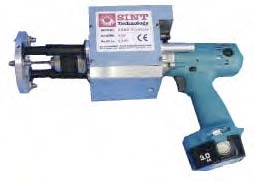
The data is also available for computer download and inclusion in the assessment report. This unique technology is unmatched for historic masonry, timber and wood evaluation and we are pleased to offer our experience and expertise in this state of the art investigation tool.
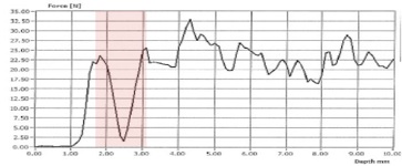
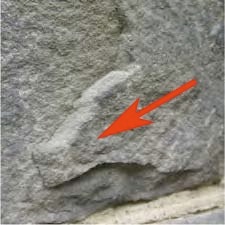
A new technique has been developed to measure the extent of deterioration of stone, mortar, brick or concrete. We are pleased to be the first consultants in North America to employ this cutting edge technology. Based on user determined parameters for the rate of advance, rate of rotation, and drill bit size (3 – 5mm), the force in Newtons is measured for the drill to advance to a preset depth. All variations in resistance are measured by on-board sensors and the graphed data can then be used to determine indirect compressive strength (50 to 50,000psi), depth of deterioration, and location of voids. The graph shows a weak resistance area corresponding to the delaminating stone. This area is in danger of spalling (see photo).
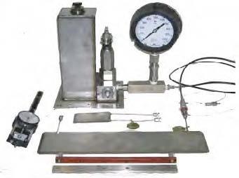
Flatjack Testing
Another technique for accessing in-situ masonry strength is via flatjack technology.
This method utilizes “bladder” jacks that can be inserted in the head and bed joints of a masonry structure, and then hydraulically loaded. By monitoring the associated deformation and strain, the stress and shear characteristics of the wall can be determined without the need to remove any of the masonry units or to take sections of the wall to the lab for testing. The equipment is equally suitable for modern CMU or historic masonry construction evaluation. For more information on flatjack test procedures, refer to ASTM C1196, C1198, and C1531 bulletins.
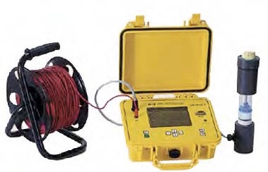
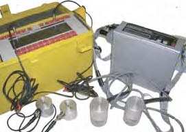
Half Cell Corrosion
Corrosion of reinforcing steel results in a change in the voltage of a current transmitted through the embedded re-bar. Half-Cell corrosion testing allows for the mapping of the extent of corrosion in the concrete, and requires a single direct point of contact with the bar to facilitate analysis of a mat of interconnected steel. The conversion of the corroding re-bar to iron oxide can result in a fifteen-fold increase in overall volume, loss of cross-sectional integrity, and tensile forces on the surrounding concrete approaching 10,000 psi. The result is concrete cracking and spalling, delamination of the concrete to steel bond, and an increase in space in which additional deterioration can occur. Determining the extent of re-bar corrosion in reinforced concrete columns, walls, slabs and decks is critical to successful repair programs.
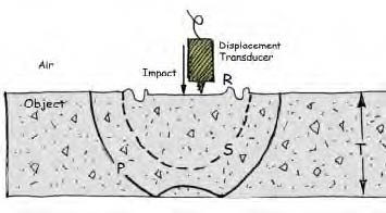
Impact Echo
Impact-Echo non-destructive testing is used to evaluate a variety of structural materials. The test method requires access to only one side of the structure and can be used to determine the quality and soundness of concrete, masonry units or wood, detect voids or decay, determine the thickness of sections, detect debonding between layers, and determine the depth of cracks or other flaws. The impact echo device imparts a stress wave to the material under evaluation and graphs the reflected wave signal, which is then interpreted. The skill and experience of the operator is critical in the acquisition and analysis of the acquired data. Below is a schematic of the stress wave (impact echo) test procedure.
Impulse Radar (GPR)
Impulse radar, better known as ground penetrating radar, is used extensively for geophysical investigations. The technique utilizes radio waves, which are transmitted through and received back from the area being investigated. In geotechnical applications, the technology can find subsurface voids, buried tanks or refuse, and other subsurface anomalies. Recently, the technology has found application in the building investigator’s toolbox. GPR equipment can detect the thickness of materials, embedded re-bar and tendons, voids below the surface of slabs, and other changes in the density of individual components or between components in a composite structure.
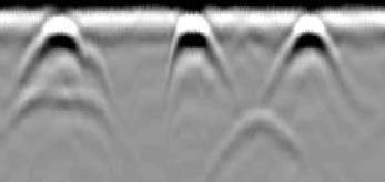
GPR data requires interpretation by a knowledgeable practitioner. See graph above.
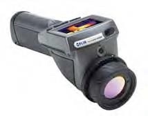
Infrared Thermography
Infrared thermography is a non-destructive method for locating structural or building envelope deficiencies. The technology is based upon the radiated energy of the area under evaluation manifested as temperature differences. The infrared camera can be used to view and document differing densities and thermal properties in materials indicative of internal deterioration, delamination and decay, and can be used to detect air leaks or water infiltration through walls, roofs, windows and decks. The use of this technology requires a thorough understanding of the conditions necessary for a successful investigation and the ability to create appropriate temperature differentials to facilitate data acquisition efforts.
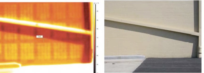
The side-by-side comparison above demonstrates the ability of the infrared camera to detect grout (or more importantly, any voids in the grout) in reinforced concrete masonry unit cells through the block shell.
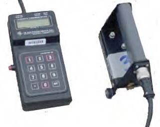
Ultrasonic
More accurately titled the acousto-ultrasonic technique, this nondestructive investigation technology utilizes an acoustic pulse to analyze the integrity of materials. The technology works most efficiently when opposing surfaces of the material are available, so the signal transducer and receiver can be aligned on opposite sides. The principle is based upon the time of flight of the signal and analysis of variations from the baseline speed. The technique is used to detect voids, delaminations and imperfections in wood, concrete or masonry structural components. Using the indirect test method (sender and receiver on the same side of the material under evaluation), ultrasonics can be utilized to detect problems in architectural elements such as stucco, EIFS, and roofing or along the surface or masonry or concrete.
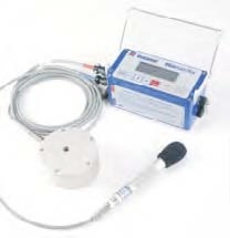
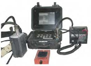
Vibration Monitoring
Often, it is necessary to anticipate potential damage to structures due to construction or other activities in their vicinity. While a careful program of documentation will provide information on the current condition, and gauges installed on the structure will note physical changes, it is desirable to monitor stress as well as strain by the use of appropriately positioned monitoring equipment. The use of vibration monitoring can be a proactive rather than reactive tool to protect buildings from damage by excessive vibration during excavation, blasting, drilling, or other nearby activities. The direct readout and immediate availability of the data can be used to correlate displacement in the structure and to set and monitor vibration limits. While not an investigation tool, this technology has applications for real time data acquisition that may help eliminate the need for an investigation should a problem associated with vibration occur.
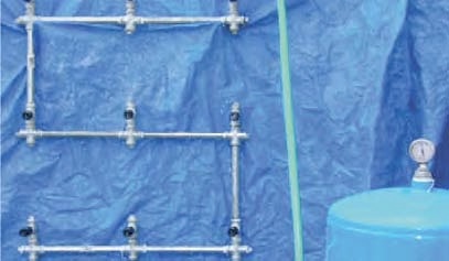
Water Penetration
The failure of building envelope components has led to field testing to determine if the exterior windows, skylights, doors and curtain walls can meet criteria established by architects, engineers and municipalities. Using a calibrated spray frame, a regulated uniform amount of water is applied to the components being tested, while a static or dynamic air pressure difference is created in a vacuum chamber mounted on the interior side. After a test of specific duration (i.e. 15 min per ASTM E1105), the chamber is removed and the component examined for water penetration. Our custom setup allows for the testing of virtually any size window or wall section under differential pressure conditions prescribed by the engineer or the local jurisdiction.